Fittings 40 to F50

Type 40 - Four Socket Cross
40.jpg (18055 bytes)

Tube Reference

mm

Kg

Type

A

B

C

D

E

F

G

H


40-5

5


32

82


0.51

40-6

6


37

92


0.60

40-7

7


46

120


1.05

40-8

8


53

136


1.46

40-9

9


62

168


2.30


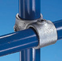
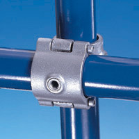
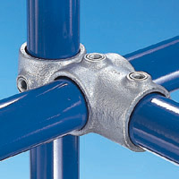
Most frequently used in multiple upright structures, to tie a center upright with horizontal tubes in four directions. The upright passes through the fitting.


Type 45 - Crossover
45.jpg (18055 bytes)

Tube Reference

mm

Kg

Type

A

B

C

D

E

F

G

H


45-2

2

2


19

16


0.02

45-3

3

3


24

21


0.07

45-4

4

4


28

25


0.13

45-5

5

5


31

34


0.23

45-6

6

6


38

40


0.29

45-65

6

5


43/37

36


0.25

45-7

7

7


46

49


0.43

45-76

7

6


46/38

45


0.45

45-8

8

8


51

55


0.32

45-86

8

6


51/38

48


0.43

45-87

8

7


51/46

51


0.62

45-9

9

9


61

67


0.50

45-98

9

8


76/76

60


0.97


Designed to give a 90 degree offset crossover joint. Frequently used on guardrailing, where, to reduce cost by minimizing the tube cuts, a continuous horizontal rail is used. Tube cannot be joined within this Kee Klamp fitting. It may be also used to give intermediate levels on racks, etc, when horizontal ties between uprights across the section are not required.

Note:Where dimension 'E' indicates two figures the 1st figure refers to socket 'A', the second refers to socket 'B' in the table.


Type A45 - Split Crossover
A45.jpg (18055 bytes)

Tube Reference

mm

Kg

Type

A

B

C

D

E

F

G

H


A45-7

7


49

46


0.65

A45-8

8


55

51


0.79


Designed to give a 90 degree offset crossover joint, tube should not be joined within the fitting.
Can be added to an existing structure without the need to dismantle the structure to attach the fitting.


Type 46 - Combination Socket Tee and Crossover
46.jpg (18055 bytes)

Tube Reference

mm

Kg

Type

A

B

C

D

E

F

G

H


46-4

4

4

4

34

28

25


0.15

46-5

5

5

5

41

31

34


0.30

46-6

6

6

6

46

38

40


0.49

46-7

7

7

7

60

46

49


0.69

46-8

8

8

8

68

51

55


0.91

46-9

9

9

9

85

61

67


1.54


Used on racking to join horizontal carrying rails to the upright, leaving the socket to take a horizontal tie across the section.
For shelved racking it is usual to have the horizontal tube outside the upright.
On pallet racking it is preferable to have the carrying rails inside the upright.


Type F50 - Female Single Socket Member
F50.jpg (18055 bytes)

Tube Reference

mm

Bolt Hole

Kg

Type

A

B

C

D

E

F

G

H

Diameter


F50-4

4


36

14

11


6.5

0.07

F50-5

5


60

25

19


10

0.28

F50-6

6


60

25

19


10

0.34

F50-7

7


68

25

19


10

0.42

F50-8

8


76

25

19


10

0.52

F50-9

9


85

26

19


10

0.65


Types F50, M50, M51, M52, and M58
These are known as swivel fittings and can be assembled as Types C50, C51, C52, and C58 or supplied as separate items.
They are frequently used for bracing, but can also overcome problems where joints are required at angles other than given by fixed angle fittings. For economical use of tubing, Types F50, sizes 5-9 only, can be combined with different sizes of M50, M51, and M52.
Types M50, M51, and M52 can be used to secure various types of infill panel (ie chipboarding, plastic sheeting, etc.)

Warning! An entire structure should not be constructed from swivel fittings,
as these would not provide sufficient stability or rigidity in the structure.


1 , 2 , 3 , 4 , 5 , 6 , 7 , 8 , 9 , 10 , 11 , 12 , 13 , 14 , 15
 
Return to the Fittings Catalogue