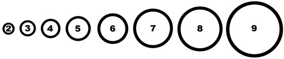
Technical Specifications

I. Tabla de tamaños

II. Table de carga

III. Prueba: Virbaciones de los conectores Kee Klamp.


Volver


Tabla de tamaños

circle sizes


Kee Klamp

Diámetro

Calibre

tamaño

O/D (mm)

Bore(mm)

2

13.5

8

3

17.5

10

4

21.3

15

5

26.9

20

6

33.7

25

7

42.4

32

8

48.3

40

9

60.3

50


Specifying Kee Klamp Fittings

The information on fittings in this site is comprehensive, and because of the coding system we have adopted, easy to use.

Diagrams are shown for each fitting showing entry of tube/pipe, a table of dimensions and a definition of use adjacent to its appropriate Type number (10, 15, 20, 25 etc.).

Alongside the Type number is a code (4, 5, 6, 7, etc.) relating to the outside diameter of the tube/pipe for which the Kee Klamp had been designed. The relationship between the Kee Klamp tube/pipe reference and standard tube/pipe outside diameter is explained in the aforementioned chart.

Example: (1) A 10-7 is a Type 10 Kee Klamp fitting with both sockets designed to accept a tube/pipe that has an outside diameter of 42.4mm or 1 11/16" (1 1/4" Nominal Pipe Size). (2) A 25-9 is a Type 25 Kee Klamp fitting with all three sockets designed to accept a tube/pipe that has an outside diameter of 60.9mm or 2 3/8" (2" N.P.S.).

Where more than one tube/pipe reference is shown alongside a particular Type number, it indicates that the individual sockets are designed to accept different sizes of tube/pipe. In a multi-digit code number the first figure relates to the 'A' socket and the second to the 'B' socket. Example (3) A 45-76 is a Type 45 Kee Klamp fitting with 'A' socket accepting a tube/pipe that has an outside diameter of 42.4mm or 1 11/16", and a 'B' socket accepting a tube/pipe that has an outside diameter of 33.7mm or 1 11/32".

While Kee Klamp can give a general guidance relating to the use of each Kee Klamp fitting detailed in this site, the nature of the product means that the ultimate responsibility for selecting the correct fitting for an application must lie with the customer.

The customer should also ensure that the existing structure to which the Kee Klamp construction is being secured, is of sufficient strength to support both the self weight of the Kee Klamp construction and the imposed loads applied, including wind loads, snow loads, and any other superimposed loads.


Arriba


Table de carga de las vigas horizantales

For uneven load distributions or single spans, the required tube size must be determined by standard bending moment calculations assuming a Kee Klamp joint to give a simply supported beam. The table shown below gives an indication only of the safe load uniformly distributed, in kg, that may be carried per shelf consisting of front and back tubes when used as continuous beams. Recommended set screw torque: 39 Nm.

At loads greater than 900 kg, consideration must be given to set screw slip.


metbeam.gif

METRIC BEAM LOAD TABLES ( kg )


KK FITTING

Size 5

Size 6

Size 7

Size 8

Size 9


SIZE OF PIPE

26.9mm x 2.6

33.7mm x 3.2

42.4mm x 3.2

48.3mm x 3.2

60.3mm x 3.6


GRADE OF MATERIAL

BS1387

BS1387

BS1387

BS1387

BS1387


SPAN (M)


SPAN (M)

0.5

540

1060

1750

2380

4000

0.5

0.6

435

850

1407

1870

3250

0.6

0.7

375

730

1207

1595

2760

0.7

0.8

330

645

1063

1385

2420

0.8

0.9

295

579

946

1230

2160

0.9

1.0

265

525

850

1110

1950

1.0

1.1

240

478

770

1013

1775

1.1

1.2

219

438

705

930

1625

1.2

1.3

202

403

651

858

1497

1.3

1.4

187

373

604

796

1387

1.4

1.5

175

347

564

741

1290

1.5


325

529

693

1205

1.6


306

499

650

1129

1.7


290

472

613

1061

1.8


277

448

581

999

1.9


268

427

553

987

2.0


408

528

944

2.1


391

505

855

2.2


376

485

818

2.3


362

467

785

2.4


349

450

755

2.5


434

728

2.6


419

703

2.7


405

680

2.8


659

2.9


639

3.0


620

3.1


603

3.2


588

3.3


575

3.4

*Note: Table values reflect a safety factor of 2:1

564

3.5


Arriba


Table de carga de las vigas verticales

This table gives an indication only of the safe load, in kg., that may be carried between the above restraints by single tubes to BS 1387 (ISO 65) when used as uprights. Loads listed under 'A' columns refer to those loads that are obtainable according to schematic 'A', and loads listed under 'B' columns refer to those loads that are obtainable according to schematic 'B'. Schematic 'B' details a racking system that is mechanically affixed to the surface on which it stands whereas schematic 'A' details a free-standing racking system. Recommended set screw torque: 39 Nm.

unfixedup.gif        fixedup.gif

METRIC UPRIGHT LOAD TABLE ( kg )


KK FITTING

Size 5

Size 6

Size 7

Size 8

Size 9


SIZE OF PIPE

26.9mm x 2.6

33.7mm x 3.2

42.4mm x 3.2

48.3mm x 3.2

60.3mm x 3.6


GRADE OF MATERIAL

BS1387

BS1387

BS1387

BS1387

BS1387


Length (M)

A

B

A

B

A

B

A

B

A

B

Length (M)

0.3

1720

1860

2950

3086

4038

4192

4783

4916

7044

7250

0.3

0.4

1435

1600

2617

2810

3703

3910

4446

4638

6661

6930

0.4

0.5

1150

1360

2284

2534

3368

3628

4109

4360

6278

6610

0.5

0.6

910

1140

1951

2258

3033

3346

3772

4082

5895

6290

0.6

0.7

725

940

1618

1982

2690

3064

3435

3804

5512

5970

0.7

0.8

590

775

1348

1706

2363

2782

3098

3526

5129

5650

0.8

0.9

480

640

1128

1471

2028

2500

2761

3384

4746

5330

0.9

1.0

N/A

540

948

1269

1752

2235

2424

3248

4363

5010

1.0


798

1092

1524

1995

2134

2970

3980

4690

1.1


N/A

937

1340

1779

1884

2692

3597

4370

1.2


1188

1587

1668

2414

3253

4050

1.3


1066

1417

1484

2169

2951

3730

1.4


N/A

1265

1328

1954

2681

3410

1.5


N/A

1130

N/A

1764

2441

3130

1.6


N/A

1602

2226

2890

1.7


N/A

1462

2032

2680

1.8


N/A

1342

1857

2480

1.9


N/A

1242

1697

2300

2.0


N/A

2120

2.1


N/A

1950

2.2


N/A

1800

2.3

*Note: Table values reflect a safety factor of 1.74

N/A

1650

2.4


Arriba


Prueba: Virbaciones de los conectores Kee Klamp.

Exhaustive tests on samples of standard size 7 Kee Klamp fittings were performed by an independent research laboratory. The purpose of the test was to evaluate the use of either standard set-screws or self-locking set screws.

Test Arrangement
A "Tee" section test assembly was made using three 300mm lengths of galvanized 1 ¼" standard pipe held together by a socket Tee fitting (Type 25-7). The vertical leg of the test assembly was supported in a standard railing flange (Type 62-7). The completed assembly was then rigidly attached to the vibration table.

The test assembly was initially assembled using standard set screws and tested in the configuration. The standard set screws were then replaced with self-locking set screws and the tests repeated.

Test Procedure
The test was conducted on a Ling 667 kg Electromagnetic vibration table.

The table was programmed to perform a resonance search between 25 and 350 Hz. The following table details the resonant frequencies that were recorded.

During the resonance search amplification factors, Q, were measured at each resonant frequency, the point of reference being the end of one horizontal pipe. The table was then held at one of the resonant frequencies, set in motion with a controlled acceleration level of 4g, and run for a period of six hours. This was repeated for three more resonant frequencies in descending order of "Q" factor.

Resonance

Frequencies

Q Factor

Running Time

74

1.27

Nil

106

1.27

Nil

158

1.53

6 hours

200

1.8

6 hours

221

5

6 hours

295

9

6 hours

During the twenty-four hours of vibration at the four resonant frequencies above no signs of loosening with either type of set screw occurred.

Arriba